Mechatronics Capstone
The Egg Catcher

Final Design - Nominated for Outstanding Design in 2020 ME Graduation!
Our approach was to use a belt and pulley system to move the catching surface with an encoder attached to the motor to provide positional feedback. We also used two photoelectric sensors at a fixed height to measure the egg’s incoming velocity. The backbone of the design was 80/20 aluminum extrusion, with most of the other parts (pulleys, sensor holders, driving gear, and catching surface) being custom designed and 3D printed ourselves.
My team and I were tasked with designing a machine that could catch a vertically falling egg using our knowledge of feedback systems (meaning a soft foam crash pad was out of the question). Our design had to be able to:
-
Sense the egg’s velocity at a known height
-
Vertically move a rigid surface to catch the egg with zero relative velocity between it and the egg
-
Catch the egg without breaking on impact or from acceleration forces while being lowered
The entire apparatus also had to be small enough to sit on a table (roughly 1 meter tall).

Photoelectric Sensors to Measure Egg's Initial Velocity
Gif Showing How Egg Will Be Caught
Much of my contribution to the project was in the derivation and simulation of the mathematical model. The areas I took leadership on included:
-
Deriving the transfer function and block diagram for the plant and the controller
-
Deriving the path that the catcher would follow based on the initial velocity of the egg
-
Using MATLAB to simulate the entire system using different constant values such as gear radius or the height of the velocity sensors to test for accuracy, error, and stability
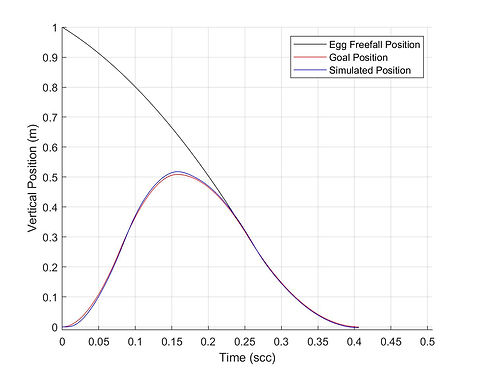
Using the path equation I derived for our catcher, I created this gif to demonstrate how the derived path will match the egg's velocity and safely lower it down. Below are a few more plots I produced comparing our theoretical and simulated position and motor torque.
.jpg)
Plot of Simulated vs. Goal Catcher Position
.jpg)
Plot of Simulated vs. Goal Motor Torque
I also played a key role in the mechanical design and helped design the catching surface and suction cup holder pictured here. Because these parts were being 3D printed, I tried to make them as simple and stable as possible so minimal supports would be needed.

Catching Surface

Suction Cup / Idler Pully Holder
Testing the Prototype
Our final design met all of the design requirements and was able to catch the egg without breaking. The prototype was such a success that it was nominated for the Outstanding Design Award in the 2020 ME graduation ceremony. Check out the video to see it in action!
Finally, here is a plot showing our goal position against actual position data taken from catching an egg. Our design very closely followed our goal position until it got to our chosen zero position where it dips far below, due to the fact that we designed our controller to be more compliant (like making a spring less stiff) once it reaches the bottom. We did this simply by reducing our controller gain after the egg had been caught.
